en-USel-GRes-ES
Menu

Appendix A


Materials
To be continued >
Introduction

Modelling slabs with finite elements in a structural frame

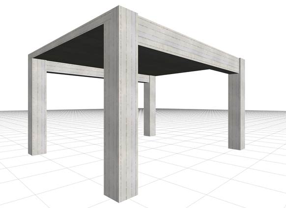
The structure of project <B_331> of the related software
(columns cross-section 400/400, beams cross-section 300/500, slab thickness 170 mm)

In order to investigate the ways that:

1)    the frame behaviour at the regions close to columns,

2)    the deflection of beams and

3)    the torsional stiffness of beams,α

affect the behaviour of slabs, two equivalent models of the simple structure illustrated in the figure, are created using the related software:

(i)    one model using members and

(ii)    one model using finite elements.


(i) Model using members

Slab modelled with members, which correspond to
2 beams b1 and b2 with cross-section 300/500,
to 6 main joists (of the slab) b3 to b8 with cross-section 500/170 and
3 secondary joists (of the slab) with cross-section 200/170
(project <B_336>, related software)

(ii) Model using finite elements

Slab model with triangular finite elements
(project <B_331>, pi-FES of the related software)


In all the following examples the pi-FES software is used and the same basic project <B_331> unchanged. Certain parameters change in some cases.

Deformed structure and cross-sections of deformed slab
(a=common beam-slab deflection)

The finite element model in all the examples of this chapter is based on the following meshing parameter values:

  • · Overall finite element size: 0.10 m
  • · Perimeter finite element size: 0.05 m

While the results are represented according to the following parameters:

  • · Stress resultants diagrams per 1.0 m along X and along Y
  • · Transparent displaced structure

In all following examples, the slab stress resultants will be compared to the stress resultants of the typical simply supported member of the slab with width 1.0 m and length 4.0 m.

In a simply supported strip of the slab the support moments are equal to 0.0 and the span moment w·l2/8=14.59·4.02/8=29.2 kNm.

In the main joist fixed at both ends the support moments are equal to -w·l2/12=-14.59·4.02/12=-19.5 kNm and the respective span moment to w·l2/24=14.59·4.02/24=9.7 kNm .


The frame behaviour in the regions close to columns
Model using members

The end main joists behave like a frame.
Negative moments at the ends (regions of columns)
should be carried by negative reinforcement.
(project <B_336>, pi-FES of related software)

 In order not to involve the issues of frame behaviour and beam torsional stiffness, the latter is considered insignificant.


In the model using members the two main end joists (of the slab) together with the columns behave as a frame. As a result, high negative bending moments are developed, Μ=-26.4 kNm corresponding to ratio (-26.4)/(-19.5)=135% of the fixed-ended member and relatively weak positive bending moments, M=+15.6 kNm in their middle, corresponding to ratio 15.6/29.2=53% of the simply supported member.

The slab model with continuous members is more accurate than the assumption of a slab simply supported along its whole length. However, in order for the actual structure to behave as designed in this case, the slab-column connection regions (edges of end main joists) should be reinforced, where (as already mentioned) high negative bending moments are developed.


The frame behaviour in the regions close to columns
Model with finite elements

project <B_331>, pi-FES of the related software

The slab model using two-dimensional finite elements provides more accurate results.

The end main strips effectively function as frames. Negative moments at the ends (regions of columns) need to be carried by negative reinforcement.

The results resemble those of the model using members with the following differences. In end main strips (corresponding to end main joists of §Α.1.1.1), the frame behaviour is more intense because support moments are higher, M=-31.8 kNm corresponding to ratio (-31.8)/(-19.5)=163% of the fixed-ended member and span moments are lower, M=+14.4kNm corresponding to 14.4/29.2=49% of the simply supported member.

First Conclusion

End strips of the slab in the regions near columns, behave as frames together with the columns, and are therefore stressed by high negative moments. It is therefore necessary to provide in these areas correctly placed and well-anchored strong, negative top reinforcement. Only if this reinforcement is placed correctly, the span frame moments of the slabs will be lower, while in case there is uncertainty about the correct placement of the reinforcement, slab model should take into account pinned supports.

For construction in common worksites, slab analysis using finite elements should assume pinned supports on columns. Except from the minimum negative reinforcement at the slab supports, increased and mainly well anchored negative reinforcement is required at the column regions.

Deflection of beams
Model using members (Supporting beams 300/1000)


The effect of beam deflections on the deformation of the slab is insignificant

Each differential deflection of beams causes a redistribution of slab moments compared to the assumption of non-deformable supports of the slabs on the beams. The question raised concerns the order of magnitude of these differences. The project <B_336> is used in 3 variations for 1000, 500 and 300 mm height of supporting beams.


Deflection of beams
Model using members (Supporting beams 300/500)

The effect of differential deformation of slab and corresponding moments is moderate.

Beam deformations continue to be significantly less than slab joists. The differential joist defor-mations in both directions cause quite small differences of moments in both directions.

Deflection of beams
Model using members (Supporting beams 300/300)

The effect of beam deflections on the deformation of slab is significant

Beam deformations are significant and they apparently affect the joists. High differential joist de-formations in both directions give significant difference of moments in both directions.

Deflection of beams
Model using finite elements (Supporting beams 300/1000)

The effect of differential deformation of slab and corresponding moments is insignificant

The project <B_331> is used in the same three variations as using the member model, i.e. with 1000, 500 and 300 mm height of supporting beams.

Deflection of beams
Model using finite elements (Supporting beams 300/500)

The effect of differential deformation of slab and corresponding moments is obvious

Beam deformations are significantly lesser than deformations of slab strips. Differential dis-placements of slab strips in both directions give small additional difference of moments in the main direction and significantly additional difference in the secondary direction.

Deflection of beams
Model using finite elements (Supporting beams 300/300)

The effect of differential deformation of slab and corresponding moments is significant

Beam deformations are significant and they visibly affect the deformations of the slab strips. High differential displacements of strips along both directions give a relatively small difference of moments in the main direction but higher additional difference of moments in the secondary direction.

Therefore, it should be noted that in the model with two-dimensional finite elements, the second-ary bending moments are always significant, while the moments in the main direction remain relatively constant.

Second Conclusion

In conclusion, the assumptions of modelling frame elements using members and modelling slabs using two-dimensional finite elements to simulate are considered to be both logical and successful Moreover, the modelling is more successful  the stronger the beams cross-section (mainly their depth) is, the smaller their span, and also the smaller the thickness of the slabs.

The regulation imposes minimum ratio of slab reinforcement in the secondary direction equal to 20% of that corresponding to the main reinforcement, to carry the secondary, computable or not, stresses.

Model using members
(a) Torsional stiffness of beams: fully elastic

Displacements and bending moments of the structure joists

The general consideration of the effect of torsional stiffness as discussed in the §3.3.4, will be applied in the project <B_331> using finite elements and in project <B_336> using members.  Cross-section of beams is 300/500.

Three cases for the effect of torsional stiffness of beams will be examined:

(a)          fully elastic

(b)          10% of fully elastic

(c)          1% of fully elastic

Bending moments of the middle joists approach more the behaviour of the fixed-ended member rather than of the simply supported member.


Model using members
(a) Torsional stiffness of beams: fully elastic

Torsional moments of the structure beams

The two beams are stressed by high torsion, due to the support moments of joists (joists are sup-ported on beams).

Model using members
(b) Torsional stiffness of beams: 10% of fully elastic

Displacements and bending moments of the structure joists

Bending moments of the middle joists approach more the behaviour of the simply supported member.

Model using members
(b) Torsional stiffness of beams: 10% of fully elastic

Beam torsional moments

The two beams are stressed by moderate torsion, due to support moments of joists (joists are supported on beams).

Model using members
(c) Torsional stiffness of beams: 1% of fully elastic

Displacements and bending moments of the structure joists

Bending moments of the middle joists correspond to the behaviour of the simply supported member.

Model using members
(c) Torsional stiffness of beams: 1% of fully elastic

Beams torsional moments

The two beams are not stressed by torsion, since the support moments of the main joists on beams are insignificant.

Model using finite elements
(a) Torsional stiffness of beams: fully elastic

Displacements and bending moments of the slab

Bending moments of strips approach the behaviour of the fixed-ended member.

Model using finite elements
(a) Torsional stiffness of beams: fully elastic

Beams torsional moments

The two beams are stressed by high torsion.

Model using finite elements
(b) Torsional stiffness of beams: 10% of fully elastic

Displacements and bending moments of the slab

Bending moments of strips reflect an intermediate condition between the simply supported member and the fixed-ended member.

Model using finite elements
(b) Torsional stiffness of beams: 10% of fully elastic

Beams torsional moments

The two beams are stressed by moderate torsion.

Model using finite elements
(c) Torsional stiffness of beams: 1% of fully elastic

Displacements and torsional moments of the slab

Bending moments of strips reflect an intermediate condition between the simply supported member and the fixed-ended member.

Model using finite elements
(c) Torsional stiffness of beams: 1% of fully elastic

Beams bending moments

The two beams are stressed by lesser but not zero torsion.

Third Conclusion

 Once the structure's formwork is removed, significant moments develop at the slab-beam connections, which are relieving slab bending and aggravating beam torsion. However, due to the creep of concrete, the torsional deformation of the beam increases gradually causing the reduction of torsional moments on the beam. The slab’s bending moments are also accordingly reduced. Gradually this slab-beam deformation tends to develop the support into pinned. To this end ECin §6.3.1(2) states that ‘… in these cases it will normally be unnecessary to consider torsion at the ultimate limit state’.


However, regardless of the calculation method, a small degree of fixity will develop at the beam-slab connection. To this end, the regulation imposes a minimum number of stirrups in beams and minimum negative reinforcement at slab support to be ≥25% of the bending reinforcement at span. Also, in case torsional stiffness is taken into account, it is recommended not to be assumed higher than the 10% of the full elastic.


FINAL CONCLUSION

The regulations, explicitly or implicitly, refer to members, in both analysis and (mainly) reinforcement design. No matter how ‘accurate’ static and dynamic analysis methods, or models of two-dimensional or three-dimensional finite elements may be used, the results (moments-shear forces) should refer always to the appropriate members, allowing the design of structures subject to bending. A slab strip can also be considered as an appropriate member. In the centroidal axis of this strip, moments and shear forces are being determined by integrating the appropriate stresses along the respective finite elements. The assumption of a structure with beams of adequate depth, providing significant stiffness to the structural frames, results in a plain space frame model consisting of members, which is reliable for both analysis and design.

In conclusion, the assumption of the members for modelling structural frames and the consideration of independent functionality of slabs are both acceptable and, under certain circumstances, form an adequately reliable solution. In finite element analysis, the common assumption adopted for slab supports is practically: slabs supported on beams with (almost) zero torsional stiffness. Regardless of the calculation method, the minimum detailing provisions of the regulations regarding the minimum reinforcement (the secondary as well as the negative one) of slabs should be followed with diligence.