en-USel-GRes-ES
Menu

Seismic accelerations

Seismic response of buildings

Seismic accelerations are induced to the structure by the seismic ground vibration. The seismic response of a structure i.e. its accelerations, induce deformations and stresses.

The structural seismic response depends on the following factors: the Seismic Zone the building belongs to, the Importance Factor, the Ground Type, the Viscous Damping, the Behaviour Factor  and of course on the magnitude and the distribution of the EI stiffnesses and masses of the building.

Hereafter the seismic response factors of buildings are considered.

Seismic zones

Map of local hazard seismic zones of Greece

The seismic ground vibration is described by the acceleration agR which denotes the reference peak ground acceleration on type A ground.

Each earthquake prone country is divided into Zones depending on the local hazard. A specific reference acceleration agR corresponds to each zone.

For instance, Greece is divided into three zones: Zone 1: agR=0.16g , Zone 2: agR=0.24g, Zone 3: agR=0.36g, where is the gravity acceleration.


Importance classes and factors γI for buildings

Class

γI

Buildings of minor importance for public safety, e.g. agricultural buildings, etc.

I

0.8

Ordinary buildings, not belonging in the other categories.

II

1.0

Buildings whose seismic resistance is of importance, in view of the consequences associated with a collapse, e.g. schools, assembly halls, etc.

III

1.2

Buildings whose integrity during earthquakes is of vital importance for civil protection, e.g. hospitals, fire stations, power plants, etc.

IV

1.4

Buildings of minor importance for public safety, e.g. agricultural buildings, etc.

 Buildings are classified in four importance classes, depending on the consequences of collapse. Each importance class has an importance factor γI usually varying between 0.80 and 1.40.
The design acceleration ag on type A ground derives from the reference acceleration multiplied by the importance factor, i.e. ag =γI×agR.

Ground type

Ground type

Description of stratigraphic profile

Parameters


vs,30 (m/s)

NSPT (blows/30cm)

cu (kPa)

A

Rock or other rock-like geological
formation, including at most 5 m of
weaker material at the surface.

> 800

_

_

B

Deposits of very dense sand, gravel, or

very stiff clay, at least several tens of

metres in thickness, characterised by a

gradual increase of mechanical properties with depth.

360 – 800

> 50


> 250

C

Deep deposits of dense or medium-dense

sand, gravel or stiff clay with

thickness from several tens to many hundreds of metres.

180 – 360

15 - 50

70 - 250

D

Deposits of loose-to-medium

cohesionless soil (with or without some

soft cohesive layers), or of

predominantly soft-to-firm cohesive soil.

< 180

< 15

< 70

E

A soil profile consisting of a surface

alluvium layer with vs values of type C

or D and thickness varying between

about 5 m and 20 m, underlain by stiffer material with vs > 800 m/s.


S1

Deposits consisting, or containing a

layer at least 10 m thick, of soft

clays/silts with a high plasticity index (PI > 40) and high water content

< 100

(indicative)

_

10 - 20

S2

Deposits of liquefiable soils, of

sensitive clays, or any other soil profile
not included in types A – E or S1


 Ground types are classified in 5 + 2 categories accounting for the influence of local ground conditions on the seismic action.
The ground type affects the acceleration magnitude, by multiplying them by the soil factor S, whose minimum value is equal to 1.0 for type A ground. It also affects the acceleration distribution, depending on each value of the natural period Τ, and in particular, on the characteristic periods TB, TC, TD of the spectrum, that correspond to the specific ground type. The values of S, TB, TC, TD which depend on the ground type are listed in the following table.

Parameter values describing the recommended Type 1 elastic response spectra

Ground type

S

TB (sec)

TC (sec)

TD (sec)

A

1.0

0.15

0.4

2.0

B

1.2

0.15

0.5

2.0

C

1.15

0.20

0.6

2.0

D

1.35

0.20

0.8

2.0

E

1.40

0.15

0.5

2.0


Viscous damping

The viscous damping is accounted for by means of the damping correction factor n determined by the expression: where ξ  is the viscous damping ratio of the structure, expressed as a percentage.

The viscous damping ratio is usually taken as being equal to 5%, thus the damping correction factor η is equal to 1.0.

Behaviour factor q

Reinforced concrete structures have the capacity to dissipate energy, mainly by means of the ductile behaviour of their elements. The structural seismic response, which is reduced by the influence of ductility, is considered in the design spectrum for elastic analysis, according to the behaviour factor q.

The behaviour factor q depends on the structural type, the regularities in plan and elevation and the ductility class.

Structural types

Concrete buildings shall be classified into one of the following structural 6+1 types according to their behaviour under horizontal seismic actions.

Column is the vertical structural element of aspect ratio lw/hw≤4, while wall is the vertical structural element of aspect ratio lw/hw>4. In the building base, VF implies the seismic shear carried by all columns, VW the seismic shear carried by all walls and Vtot= VF + VW the total seismic shear at ground floor level.

1.    Frame system

Structural system comprising only columns, or both columns and walls, in which columns are the main resisting elements with VF/Vtot>0.65.

2.    Ductile wall system (coupled or uncoupled)

Structural system comprising only walls, or both columns and walls, in which walls are the main resisting elements with VW/Vtot>0.65.

3.    Frame-equivalent dual system

Structural system comprising both columns and walls with 0.50<VF/Vtot≤0.65.

4.    Wall-equivalent dual system

Structural system comprising both columns and walls with 0.50<VW/Vtot≤0.65.

5.    System of large lightly reinforced walls

System comprising at least two walls in the horizontal direction considered satisfying the three following conditions:

  • The horizontal dimension is lw≥min(4.0 m, 2hw/3),
  • The walls collectively support at least 20% of the total gravity load from above in the seismic design situation.
  • The fundamental period of the structure is ≤0.5 sec

If the first of the above conditions is satisfied but either the second or the third is not, then the system is classified as ductile wall system and all of its walls should be designed and detailed as ductile walls.


6.    Inverted pendulum system

System in which 50% or more of the mass is in the upper third of the height of the structure.


One-storey frames with column tops connected along both main directions of the building and with the value of the column normalized axial load νd exceeding 0.3 nowhere, do not belong in this category.

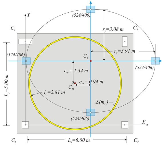
7.    Torsionally flexible system [EC8, 5.2.2.1(4)P]

Provided that at the characteristic floor either rx<ls, or ry<ls is satisfied, then the system is classified as torsionally flexible. In the floor of the example min(rx, ry)= min(3.91, 3.08)=3.08 m >ls=2.81 m, thus the building is not  torsionally flexible.


Regularity in plan

For a building to be categorised as being regular in plan, it shall satisfy all the following conditions:

  1. With respect to the lateral stiffness and mass distribution, the building structure shall be approximately symmetrical in plan with respect to two orthogonal axes.
  2. Each floor shall be delimited by a polygonal convex line. If in plan set-backs exist, regularity in plan may still be considered as being satisfied, provided that these setbacks do not affect the floor in-plan stiffness. For each set-back, the area between the outline of the floor and a convex polygonal line enveloping the floor does not exceed 5 % of the floor area.
  3. The in-plan stiffness of the floors shall be sufficiently large in comparison with the lateral stiffness of the vertical structural elements, in order to satisfy the rigid diaphragm condition. This condition is usually satisfied in reinforced concrete structures.
  4. The slenderness λ of the building in plan shall be λ=Lmax/Lmin≤4
  5. At each level shall be:
    eox≤0.30rx & eoy≤0.30ry [provided is not flexible at the same time, i.e. min(rx, ry)≥ls ]


Example:

Consider eox=0.94 m≤0.30rx=0.30×3.91=1.17 m, but eoy=1.34 m>0.30ry=0.30×3.08=0.92 m which does not satisfy the necessary condition, thus the building comprising that specific floor is not considered as being regular in plan.


Regularity in elevation (i)

regular in elevation building

non-regular in elevation building
(change of column dimension)

non-regular in elevation building
(interrupted column)

non-regular in elevation building
(planted column)

regular in elevation building
(column added of in the basement)

regular in elevation building
(The top of the building
does not count as floor)

For a building to be categorised as being regular in elevation, it shall satisfy all the following conditions:

All lateral load resisting systems, such as cores, structural walls, or frames, shall run without interruption from their foundations to the top of the building or, if setbacks at different heights are present, to the top of the relevant zone of the building. Cases of regular and non-regular in elevation buildings are presented in the abone figures.


Regularity in elevation (ii-a)

ii) Both the lateral stiffness and the mass of the individual storeys shall remain constant or reduce gradually, without abrupt changes, from the base to the top of a particular building.

The storey stiffness is defined as the ratio of the applied seismic force το the relative lateral stiffness (or equivalently, the displacement of the centre of stiffness).

In the absence of particular data provided by the EC8, the limit values for the stiffness and mass fluctuation may be taken as being equal to:

Mass increase  ΔMi=(Mi+1-Mi)≤0.35Mi,

Mass reduction ΔMi=(Mi-Mi+1)≤0.50Mi,

while for each main horizontal direction x, y


Relative stiffness increase ΔKi=(Ki+1-Ki)≤0.35K, Relative stiffness reduction ΔKi=(Ki-Ki+1)≤0.50Ki


Regularity in elevation (ii-b)

Non-regular in elevation, due to
significant stiffness difference (soft storey)

Non-regular in elevation, due to
significant mass difference (loft)

The stiffness ratio fluctuation is very sensitive. The most critical factor is the interstorey height since it is involved directly or non-directly in the calculation of the column stiffness raised in the 3rd power. For instance, in case of two storeys with the same columns, the same loads and interstorey heights equal to 4.0 m and 3.0 m, respectively, the first is (4.0/3.0)3=2.4 times more flexible than the second and thus the building is considered as being non-regular in elevation. For interstorey height 6.0 m, instead of 4.0 m, the corresponding ratio yields (6.0/3.0)3= 8. Such stories are called soft storeys having an unfavourable effect both on defining the building as being irregular in elevation, and on the stress and strain behaviour of the building.

Consider a building where two consecutive storeys have the same walls and frames but the first one has less slabs, e.g. as in mezzanines, then the  second carries less loads than the first. That could affect the uniform mass distribution, resulting in the building being considered as non-regular in elevation.

Regularity in elevation (iii)

iii)      In framed buildings the ratio of the actual strength of columns and beams to the strength required by the analysis should not vary disproportionately from the corresponding overstrength factor between adjacent storeys.            
For each floor and each direction the column resistance moments ΣMc,Rd  in both directions (+x, -x) και (+y, -y) and the two corresponding beam resistant moments ΣMb,Rd are added. 

Regularity in elevation (iv): (a)


It shall be 

iv) When setbacks are present, the following additional conditions apply for each direction:

(a) For gradual setbacks preserving axial symmetry, the setback at any floor shall be not greater than 20 % of the previous plan dimension in the direction of the setback.

Regularity in elevation (iv): (b)


It shall be

      and

iv) When setbacks are present, the following additional conditions apply for each direction:

(b) If the setbacks do not preserve symmetry, in each face the sum of the setbacks at all storeys shall be not greater than 30 % of the plan dimension at the ground floor above the foundation or above the top of a rigid basement, and the individual setbacks shall be not greater than 10 % of the previous plan dimension.

Regularity in elevation (iv): (c)


It shall be

(iv): (c) For a single setback within the lower 15 % of the total height of the main structural system, the setback shall be not greater than 50 % of the previous plan dimension. In this case the structure of the base zone within the vertically projected perimeter of the upper storeys should be designed to resist at least 75% of the horizontal shear forces that would develop in that zone in a similar building without the base enlargement.

Ductility classes

Earthquake resistant buildings are classified in three ductility classes.

(a) DCL from the initials of Ductility Category Low

(b) DCM from the initials of Ductility Category Medium

(c) DCH from the initials of Ductility Category High

DCL

Buildings belonging to Ductility Category Low are designed for low energy dissipation capacity and low ductility, following the provisions of EC2 that concern the dimensioning without of course accounting for the reduction of seismic forces, i.e. the behaviour factor q shall be taken equal to 1.0. The only construction requirement concerns the use of B or C steel class [EC2, 3.2.2(3)A].

This category is recommended for the classification of buildings in low seismicity regions.

DCM

Buildings belonging to Ductility Category Medium are designed for medium energy dissipation capacity and medium ductility, and conform to the particular design and construction rules of EC8.

DCH

Buildings belonging to Ductility Category High are designed for high energy dissipation capacity and high ductility and conform to the strictest relevant design and construction rules.

Buildings classified as frame system and brittle masonry are not allowed to belong to this class.

Basic value of the behaviour factor qo


DCM

DCH

Structural type

Regular in elevation

Non-Regular in elevation

Regular in elevation

Non-Regular in elevation

Inverted pendulum system (6)

1.5

1.2

2.0

1.6

Torsionally flexible system (7)

2.0

1.6

3.0

2.4

Uncoupled wall system [partial case (2)]

3.0

2.4

4.0au/a1

3.2au/a1

Frame system (1), dual system (3), (4), coupled wall system (2)

3.0au/a1

2.4au/a1

4.5au/a1

3.6au/a1

Values of the multiplication factor au/a1

Structural type

Building type

Κανονικό σε κάτοψη

Μη κανονικό σε κάτοψη


au/a1

au/a1

Frame system (1), frame-equivalent dual system (3), (4), coupled wall system (2)

One-storey building

1.10

1.05

Multistorey building with one-bay frame in the direction considered

1.20

1.10

Rest of multistorey buildings

1.30

1.15

Ductile wall system (2)


1.20

1.10

Wall-equivalent dual system (4)

Two walls in the direction considered

1.00

1.00

More than two walls in the direction considered

1.10

1.05

Systems of large lightly reinforced walls (5)


1.00

1.00

The factor au/a1 does not need to be evaluated for inverted pendulum(6) or torsionally flexible(7) systems.

Basic value of the behaviour factor qo

Structural type

Ductility class

DCM

DCH


au/a1

aqo

(6)

inverted pendulum system


1.0

1.5

2.0

(7)

torsionally flexible system


1.0

2.0

3.0

(5)

System of large lightly reinforced walls


1.0

3.0

4.0

(4)

Wall-equivalent dual system

Two walls in the direction considered

1.0

3.0

4.5

More than two walls

1.1

3.0

4.5

(3) & (1)

Frame or wall-equivalent dual system

One-storey building

1.1

3.0

4.5

Multistorey building with one-bay frame in the direction considered

1.2

3.0

4.5

Rest of multistorey buildings

1.3

3.0

4.5

(2)

Ductile wall system

Uncoupled walls in the direction considered

1.2

3.0

4.0

Coupled walls in the direction considered

1.2

3.0

4.5

regular in elevation– regular in plan:qo=aqo·au/a1

regular in elevation– non-regular in plan: qo=aqo·(1+au/a1)/2

non-regular in elevation – regular in plan:qo=0.8·aqo·au/a1

non-regular in elevation – non-regular in plan: qo=0.8·aqo· (1+au/a1)/2

Failure mode factor kw

The behaviour factor is given by the expression q=kwqo≥1.5, where qο is the basic value of the behaviour factor, presented in the previous paragraph and kw is the failure mode factor.

kw=1.0 for frame systems (1), or frame-equivalent dual systems (3), while for the remaining wall systems (2), (4), (5), Kw=(1+ao)/3, where ao is the aspect ratio of the walls equal to ao=Σhw,i/Σlw,i. In any case kw should satisfy the relation 0.50≤kw≤1.0.

The failure mode factor kw is ≤1.0 provided that ao≤2.0, meaning walls of average length lw>hw/2, i.e. in a one-storey building of height hw=3.0 m for walls of length lw>3.0/2=1.50 m, in a two-storey building of hw=2×3.0=6.0 m for walls of lw>6.0/2=3.0 m and, respectively, in a similar four-storey building for walls of lw>6.0 m and for a ten-storey building for walls of lw>15 m. For common multistorey buildings without large lightly reinforced walls, applies kw=1.0.

Text/HTML

Text/HTML

Conclusion

A few brief results, based on the previous paragraphs, are presented here:

·         For common buildings, the behaviour factor q is equal to the basic behaviour factor qo, i.e. q=qo.

·         For DCM q varies between 1.50 and 3.90 while, for DCH q varies between 1.60 and 5.85.

·         In inverted pendulum systems (6) q is independent of the regularity in plan. For DCM q, is also independent of the regularity in elevation and is equal to 1.50, while for DCH q is equal to 1.60 or 2.0.

·         In torsionally flexible systems (7) q is independent of the regularity in plan. For DCM q is 1.60 or 2.0 while for DCH is 2.40 or 3.0.

·         In wall-equivalent dual systems (4), for DCM q varies between 2.40 and 3.30 while for DCH q varies between 3.60 and 4.95.

·         In ductile wall systems (2), for DCM q varies between 2.88 and 3.60 while for DCH q varies between 3.60 and 5.40.

·         In frame (1) or frame-equivalent dual systems (3), the maximum values of q apply. For DCM q varies between 2.88 and 3.90 while for DCH q varies between 4.32 and 5.85. The seismic design of masonry frame systems is not allowed, in general.

·         The minimum value of the behaviour factor, q=1.50, may be selected for every simple or complex building, without structural type classification or regularity criteria compliance. Such selection beyond the safety reasons also covers the case of radical structural change due to renovation, change of use or other reason, during the building lifetime.

The assumption of q=1.0 combined with the classification, regarding the construction rules, to DCM or even better to DCH, is definitely a good choice for the seismic design of buildings. Certainly, if the building is designed appropriately, achieving value of q higher than e.g. 3.50, high standards of safety would be reached.

Design spectrum of horizontal seismic actions

For the horizontal components of the seismic action the design spectrum, Sd(T), is defined by the following expressions:

0 ≤ T < TB:        

TB ≤ T < TC:    

TC ≤ T < TD:    

TD ≤ T:      

The recommended value, provided by the EC8, for β is 0.20.