en-USel-GRes-ES
Menu

Cantilevers, one way slabs


Materials
To be continued >
Introduction

Static analysis

Static analysis of cantilevers (as well as one-way slabs) takes into account that loads are applied on 1.00 m wide strips.


Example of deflection calculation


Cantilever slab with thickness h=200 mm, length L=2.00 m and concrete C40/50, is subjected to covering load gεπ=1.0 kN/m2, live load q=5.0 kN/m2 and concentrated load G=4.0 kN/m applied at the end.

Calculate bending moments, shear forces and deflections in ultimate limit state.

Solution

Loads

Consider strip width b=1.00 m.

Self-weight:

go=γ (b (h=25. 0kN/m3 (1.00m (0.20m=5.0 kN/m

Covering load:

ge=1.0kN/m2·1.00m=1.0 kN/m

Total distributed dead load:

g=go+ge=5.0+1.0=6.0 kN/m

Dead concentrated load:

G=4.0kN/m·1.00m=4.0 kN

Live load:

q=5.0kN/m2·1.00m=5.0 kN/m

Design loads

p=γg·g+γq·q=1.35·6.0+1.50·5.0=15.6 kN/m

P=γg·G=1.35·4.0kN=5.4 kN

Design shear forces

VA=P+p·L=5.4+15.6·2.00=36.6 kN

Vk=VA-p·L=36.6-15.6·2.00=5.4 kN

Design bending moments

MA=-P·L-p·L2/2=-5.4·2.00-15.6·2.002/2=-42.0 kNm

Mk=0

Deflections

For C40/50 it is E=35.2·109 Pa [EC2, 3.1.2] and from volume C’ §1.1

I=b·h3/12=1.00·0.203/12=6.67·10-4 m4

E·I=35.2·109N/m2·6.67·10-4m4=234.8·105 N·m2

Due to uniformly distributed load p:


Due to concentrated load P:


In total: ymax=ymax,1+ymax,2=1.33+0.61=1.94 mm

General

One-way slabs are those supported on two opposite edges.
If a one-way slab is supported on more than two edges and its aspect ratio, i.e. the ratio of the larger to the smaller theoretical span, is greater than 2.0 (such as slab s3 in the same figure), it is considered as one-way slab in the principal direction while taking into account the secondary stresses in rest edges.

Static analysis

Continuous one-way slabs are analysed considering a frame of continuous member s of rectangular shape cross-section, having width equal to 1.00 m and height equal to the thickness of the slab. The strip loads comprise self-weight, dead and live loads.

Analysis is performed:

a) approximately, by applying all design loads p=1.35g+1.50q (when live load is relatively small)

b) accurately, by taking into account unfavourable loadings.

Example: Three-span continuous slab

Bending moment diagram

The three slabs (previous figure) have L1=4.50 m, h1=180 mm, g1=10.0 kN/m2, q1=2.0 kN/m2, L2=4.00 m, h2=140 mm, g2=5.0 kN/m2, q2=2.0 kN/m2, L3=4.00 m, h3=140 mm, g3=5.0 kN/m2, q3=2.0 kN/m2, where loads g include self-weight. Perform static analysis considering global loading in ultimate limit state.

Design load in each slab is equal to pi=γg×gi+γq×qi=1.35×gi+1.50×qi, thus on 1.00 m wide strip, it is:

p1=1.35×10.0+1.50×2.0=16.5 kN/m

p2=p3=1.35×5.0+1.50×2.0=9.75 kN/m

The three-span continuous slab will be solved through Cross method.

Fundamental design span moments (table b3)

M10=-p1×L12/8=-16.5×4.502/8=-41.8 kNm

M12=M21=-p2×L22/12=-9.75×4.002/12=-13.0 kNm

M23=-p3×L32/8=-9.75×4.002/8=-19.5 kNm

Moments of inertia I

I01=Ic=1.0×0.183/12=4.86×10-4 m4

I12=I23=1.0×0.143/12=2.29×10-4 m4=0.47Ic

Stiffness factors k, distribution indices υ


V01=16.5×4.50/2-22.6/4.50=32.1 kN

V10=-16.5×4.50/2-22.6/4.50=-42.1 kN

V12=9.75×4.00/2+(-13.9+22.6)/4.00=21.7 kN

V21=-9.75×4.00/2+(-13.9+22.6)/4.00=-17.3 kN

V23=9.75×4.00/2+13.9/4.00=23.0 kN

V32=-9.75×4.00/2+13.9/4.00=-16.0 kN

maxM01=32.12/(2×16.5)=31.2 kNm

maxM12=21.72/(2×9.75)-22.6=1.5 kNm

maxM23=16.02/(2×9.75)=13.1 kNm


The elastic line of the three slabs (from the equations)

The elastic line of the three slabs

Front view of the elastic line (from pi-FES with active module\SLABS) (project <B_451>)

Effect of live load on the static analysis of one-way slabs
Accurate analysis method (1)


Analysis with minimum design dead loads gd,i=1.0gi

The accurate analysis of continuous one way slabs is performed by superimposing the following loadings (unfavourable loadings).


Effect of live load on the static analysis of one-way slabs Accurate analysis method (2)

Analysis with maximum design live loads qd,i=0.35gi+1.50qi

Maximum and minimum span moments alternating loading on spans)


Effect of live load on the static analysis of one-way slabs Accurate analysis method (3)

Analysis with maximum design live loads qd,i=0.35gi+1.50qi

Minimum support moments 

(continuously loading on adjacent spans and alternating with the rest)


Effect of live load on the static analysis of one-way slabs
Accurate analysis method (4)


 Analysis with maximum design live loads qd,i=0.35gi+1.50qi
Maximum support moments (void loading on adjacent spans and alternating with the rest)

Example

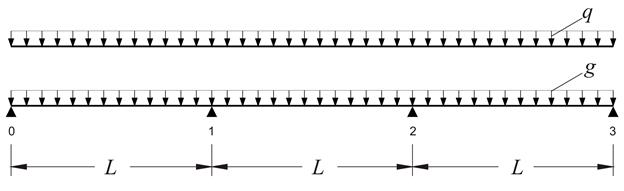
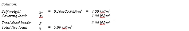
The continuous slab shown in the figure, of span length L=5. 00 m and of thickness h=160 mm, is subjected to covering load ge=1.0 kN/m2 and live load q=5.0 kN/m2. Concrete class C50/60. Calculate the shear forces and bending moments envelopes for the three slabs, in ultimate limit state.

 The design dead load for each slab is gd=1.00·5.0=5.0 kN/m and the total design load is pd=γg·g+γq·q=1.35·5.0+1.50·5.0=14.25 kN/m.

Manual calculations:   I=(b·h3)/12=(1.0·0.163)/12=341·10-6 m4

Modulus of elasticity for concrete C50/60 is equal to E=37.3 GPa.

E·I=37.3·109N/m2·341·10-6m4=12.719·106 N·m2

For I10=I12=I23=Ic, stiffness factors k distribution indices υ are:


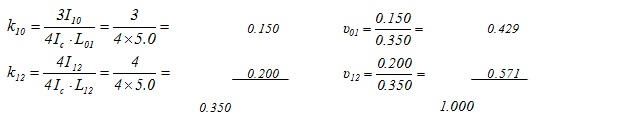
Due to frame symmetry:  και 

Loading 1: w1=w3=pd=14.25 kN/m, w2=gd=5.0 kN/m (V01,max, M01,max, M12,min, |V32,max|, M23,max)

Loading 2: w1=w3=gd=5.0 kN/m, w2=pd=14.25 kN/m (V01,min, M01,min, M23,max, |V32,min|, M23,min)

Loading 3: w1=w2=pd=14.25 kN/m, w3=gd =5.0 kN/m (V12,max, |V10,max|, M1,min)

Loading 4: w1=gd=5.0 kN/m w2=w3=pd=14.25 kN/m, is an antisymmetric case of loading 3 with respect to the middle.

Envelopes of the results of all loadings

Analysis using the software (project <<B_453-1>)

Shear force envelope for q=5.0 kN/m2


Bending moment envelope for q=5.0 kN/m2


Deflection envelope for q=5.0 kN/m2

The analysis of continuous slabs under global loading pd=14.25 kN/m

Shear force diagram for p=14.25 kN/m

Bending moment diagram for p=14.25 kN/m

Deflection diagram for pd=14.25 kN/m 

Comparing the results of analysis with global loading and unfavourable loadings, relatively small differences regarding shear forces are noticed, while significant differences regarding span bending moments and deflections are mainly registered at the mid-span.

Effect of live load on the static analysis of one-way slabs
Simplified method for envelope estimation

2 spans

3 spans

4 spans

Infinite spans

Unfavourable loadings may not be considered in static analysis of slabs of common buildings, provided that the support and span bending moments are multiplied by an incrementation factor according to the following.

  • ·In case of one way slabs with almost equal spans and load ratio "dead" / "live" = gd/qd = 1.0g / (0.35g + 1.50q) 1.0 or gd/pd = 1.0g / (1.35g+1.50q) 0.50 (valid for most cases of loads used for resintential design), the incrementation factors of bending moments may be taken from the above table.

  • ·In case of two-way slabs having almost equal spans, similar increments are valid although reduced by 50%.

  • ·Regarding shear forces, the average increment for all support types is approximately 10%.