en-USel-GRes-ES
Menu

Two-way slabs


Materials
To be continued >
Introduction

Definition

A slab supported on all four edges with an aspect ratio of longer to shorter theoretical span less than ≤2.00, is considered to be two-way.
Static analysis of two-way slabs, subjected to uniform load, is performed using tables, which give the fundamental support moments, span moments and shear forces.
In these tables, each slab is characterized by a number from 1 to 6, depending on the type of support, as illustrated in the figure.
The floor diaphragm, as a rule, consists of many connected slabs affecting each other. The ac-curate calculation of these influences is performed only by means of two dimensional finite ele-ments. In usual cases, shear and reaction forces are not affected by adjacent slabs. An addition-al reason for considering slabs isolated, is to use simplified methods for the calculation.

Shear forces and support reaction forces
Simplified method

Distribution of load is considered as triangular or trapezoidal. Heights of triangles/trapezoids determine the maximum values of load transferred to the corresponding points of the peripheral support. These maximum loads are the maximum shear forces Vi,j of the slab, while equivalent loads pi,j represent the equivalent uniform reactions.

Values of coefficients of shear forces and equivalent uniform reactions


Vxrxr·p·lx


Vxermxerm·p·lx


Vyr= ρyr·p·lx


Vyerm= ρyerm·p·lx


pxrxr·p·lx


pxermxerm·p·lx


pyr= υyr·p·lx

pyerm= υyerm·p·lx

The values of coefficients of shear forces Vi,j and equivalent uniform reactions pi,j are given in the six tables b5.1 to b5.6 cited  in the end of the book.

In each of six support cases two triangles and trapezoids are formed in directions x, y or conversely (depending on the side ratio). 


Shear forces and equivalent uniform reactions
Czerny’s elasticity method

Shear force diagram by Czerny for side ratio 1.50

According to the theory of elasticity, the distribution of shear forces along the length of the four edges of a slab, results from the shear forces along its perimeter as described by equations. The most unfavourable shear forces along the sides of a slab (as well as the most unfavourable bending moments) are tabulated in the tables of the book entitled “Applications of Reinforced Concrete” (p46-51 for two-way slabs, p52-59 three- or two-side-supported slabs) of series of books by Apostolos Konstantinidis published in1994.

Fundamental support and span moments – Deflections
MARCUS method

In this method, the slab is replaced by two intersecting strips along directions x and y respectively, which meet in its middle point m.

Depending on the support conditions, the strips are classified as simply supported, fixed at one end or fixed at both ends.

Each strip, subjected to its corresponding load, provides an elastic line and a bending moment diagram.

Simply supported strip

(where i=x,y) 

Strip fixed at one end


Strip fixed at both ends


Fundamental support and span moments – Deflections
CZERNY’s elasticity method


Bending moments in continuous two-way slabs
Continuous strip method

The coefficients used for the determination of spans and supports bending moments result from the tables depending on the aspect ratio (where in lx is the shortest dimension) and the type of support. 

Thus:


Bending moments in continuous two-way slabs
Accurate method (manual)

Stiffness coefficients and transfer indices of each slab depend on its type of support and its aspect ratio. These data are provided by tables in several books, e.g. by Hahn.

All supports are considered fixed when principal moments are calculated.

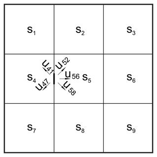
One support is freed, e.g. 45 of the figure, and distribution takes place on all directions (i.e. CROSS method on plane).

This procedure is repeated until moments balance.

Such a solution is, certainly, complex and laborious, but it is applicable in case of large spans with significant differences in dimensions and thicknesses.


Bending moments in continuous two-way slabs
Practically accurate method

In usual cases of slabs with almost the same thickness (even for large or uneven spans), support moments are calculated with reasonable accuracy according to the expression:

, where  and  are the principal moments at support 1.

Support moments affect at minimum level span moments, resulting the latter to be calculated considering rigid supports.

This particular method is applied in the majority of practical problems, as it combines adequate accuracy (much more accurate than the strip method) with high speed application.


Influence of live load

The general case of unfavourable loadings is described in §4.2.3 for every type of slab. This paragraph focuses on imposing and determining unfavourable loadings in the special case of a symmetric group of two-way slabs.

Unfavourable loadings are always considered as of zatrikion (chess) form. This property leads to the consideration of two equivalent loading cases, one with uniform positive loads of equal magnitude and another of zatrikion form with uniform loads of equal magnitude but alternating sign.

This technique is applied in the next example. It is worth noting that the paragraph containing the exercises of this chapter deals with the analysis of a large symmetric group of two-way slabs.


Example

Determine the moments for ultimate limit state of the slabs illustrated in the figure;
covering loads g
επ=1.5 kN/m2 and live loads a) q= 2.0 kN/m2, b) 5.0 kN/m2, c) 10.0 kN/m2.


 project <Β_464>


Static analysis

To determine the critical support moment, both slabs are loaded by the total load:

pd=1.35g+1.50q

For the determination of maximum and minimum spam moments, one slab is loaded by the minimum design load gd=g and the other is loaded by the minimum one pd=1.35g+1.50q.

The two following independent loadings p1 and p2 are considered:

p1=g+(0.35g+1.50q)/2

p2=(0.35g+1.50q)/2

It is:

gd=p1-p2 και pd=p1+p2


Dead load is equal to:

g=0.15x25.0+1.5=5.25 kN/m2, οπότε για


a) For live load q=2.0 kN/m2

p1=5.25+(0.35x5.25+1.5x2.0)/2= =5.25+2.42=7.67 kN/m2
p2=(0.35g+1.50q)/2=2.42 kN/m2
à
gd=p1-p2=5.25 & pd=p1+p2=10.09 kN/m2


b) For live load q=5.0 kN/m2

p1=5.25+(0.35x5.25+1.5x5.0)/2= =5.25+4.67=9.92 kN/m2,
p2=(0.35g+1.50q)/2=4.67 kN/m2
à
gd=p1-p2=5.25 & pd=p1+p2=14.59 kN/m2


c) For live load q=10.0 kN/m2

p1=5.25+(0.35x5.25+1.5x10.0)/2= =5.25+8.42=13.67 kN/m2

p2=(0.35g+1.50q)/2=8.42 kN/m2 à
gd=p1-p2=5.25 & pd=p1+p2=22.09 kN/m2


 Each slab is solved for two types of support by means of proper coefficients for aspect ratio .


Table b5.2 for slab s1(one fixed edge and the rest simply supported) gives  kx,1=0.453, ky,1=0.547, vx,1=0.738, vy,1=0.631, while table b5.1 for slab s1 (simply supported all four edges) gives kx,2=0.675, ky,2=0.325, vx,2=vy,2=0.610.

Support moment s1-s2

The most unfavourable support moment results from the maximum loading pd of both slabs. Since both geometry and loading are symmetric static behaviour of the slabs is identical. Consequently the support moment s1-s2 is equal to the fixity moment of each slab.


a) For live load q= 2.0 kN/m2


b) For live load q= 5.0 kN/m2


c) For live load q= 10.0 kN/m2


 Span moments

The maximum moment of each span results from loading one span with pd and the other span with gd, as shown in the first out of the three following figures. These loadings are equal to pd=p1+p2 and gd=p1-p2 respectively. Analysis is performed by means of equivalent loadings using p1 and p2.

Both 1st equivalent loadings are symmetric, thus both slabs function as fixed on one edge and simply supported on the rest. On the contrary 2nd equivalent loadings are antisymmetric, thus both slabs function as simply supported on all four edges. Consequently the two individual analyses as well as their resultants will be accurate.


loading of upper slab

1st loading of upper slab

+

2nd loading of upper slab


Figure 4.6.4-5


Loading of lower slab

1st loading of lower slab

+

2nd loading of lower slab


(1) elastic line , (2) moment diagram

Slabs supported on three edges

A three-edge-supported slab is the one supported along three edges.

Static analysis is performed similar to two-way slabs (i.e. considering each individual slab), by means of tables e.g. by Hahn.

Moments are practically distributed according the approximate method of § 4.6.3.3.

The tables support global uniform loads, continuous linear uniform loads on free edges and continuous linear moments on free edges.

A slab of shape Γ

is analyzed considering one three-edge-supported slab and one two-way slab, as shown in figure below. This method is proposed by Hahn and it requires particular attention reinforcing the slab. Indicatively, it is emphasized that continuous reinforcement should be placed along the lower fibers at the theoretical boundary of the two-way slab and the three-edge-supported slab.


Slabs supported on two adjacent edges

A two-edge-supported slab is the one supported on two adjacent edges.

Static analysis is performed similar to two-way slabs, by means of tables e.g. by Stiglat.

Special attention should be paid to the reinforcement distribution, which has to be compatible with that of the corresponding moment distribution.

Near edges, these slabs behave practically as cantilevers (of course depending on the aspect ratio ly/lx), such as the slab section with length lx-ly illustrated in the figure.