To determine the deformation developed by external moment M, applied at the centre of stiffness CT, the initial system X0Y is transferred (by parallel translation) to the principal system xCTy. The centre of mass is transferred to the principal system along the structural eccentricities eox, eoy in accordance with the following expressions:
Principal coordinate system
 ,
,  ,
,  ,
,  (6’)
(6’)
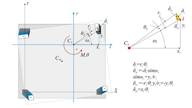
The displacement of the diaphragm consists essentially of a rotation θz about the CT, inducing a displacement δi at each column top i with coordinates xi,yi in respect to the coordinate system with origin the CT. If the distance between the point i and the CT is ri, the two components of the (infinitesimal) deformation δi are equal to δxi=-θz·yi and δyi=θz·xi.
The shear forces Vxi and Vyi in each column developed from the displacements δxi, δyi are:
Vxi=Kxi·δxi=Kxi·(-θz·yi) → Vxi=-θz·Kxi·yi and Vyi=Kyi·δyi=Kyi·(θz·xi) → Vyi=θz·kyi·xi
The resultant moment of all shear forces Vxi, Vyi about the centre of stiffness is equal to the external moment MCT, i.e.
MCT=Σ(-Vxi·yi+Vyi·xi+Kzi) → MCT= θz·Σ(Kxi·yi2+Kyi·xi2+Kzi)
Torsional stiffness Kzi of column i
Columns resist the rotation of the diaphragm by their flexural stiffness expressed in terms Kxi·yi2 , Kyi·xi2 (in N·m), and their torsional stiffness Kzi, which is measured in units of moment e.g. N·m.
The torsional stiffness of a column is given by the expression Kz=0.5E·Id/h, where 0.5Ε is the material shear modulus G, usually taken equal to 0.5 of the elasticity modulus, h is the height of the column and Id is the torsional moment of inertia of the column’s cross-section, taken from the following table.
Torsional stiffness of the floor diaphragm
 , where
 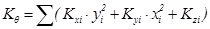 (7’)
(7’)
The quantity Κθ is the torsional stiffness of the diaphragm and is measured in N·m. The quantities Kx=Σ(Kxi), Ky=Σ(Kyi), measured in N/m, imply the lateral stiffnesses of the diaphragm in x and y direction respectively.
Definitions:
Lateral stiffness Κj of diaphragm denotes the force in direction j required to cause a relative parallel displacement of the diaphragm by one unit in considered direction.
Torsional stiffness Kθ of diaphragm denotes the moment required to cause relative rotation of the diaphragm by one unit.
Note
The torsional stiffness of columns Kz is very small and is usually omitted.