en-USel-GRes-ES
Menu

Deformation-Stresses


Materials
To be continued >
Introduction

Frame model


                                        Woodwork plan                                                           Section Α-Α


The structure consists of four columns, two beams and a slab <project B_331>

In order to understand the concepts of the static and seismic behaviour of the buildings, a single-storey structure is examined. The structure consists of two frames (each frame consists of two columns connected to one beam) and a slab. Foundations are not taken into account, while columns are considered fully restrained (fixed) at their base.

The structure in 3-D

Slab analysis


The equivalent member, simply supported at both ends, of the slab strip

The slabs of reinforced concrete structures can be modelled as members with width 1.0 m simply supported on beams. In this example, slab s1 is simply supported at both ends with width h =170 mm , and span l =4.00 m . Τ he design stress resultants, result from the slab's self-weight and covering loads and a live load q =5.00 kN/m2

Total dead loads: g =5.25 kN/m  Total live loads: q=5.00 kN/m

 The design combination derives from the design load psd=γg×g+γq×q= 1.35g+1.50q=14.59 kN/m,

VAd=-VBd=14.59×(4.00/2)=29.18 kN,  Mmd=14.59×(4.002/8)=29.18 kNm

Slab together with beams and columns behave as one structure in which each member affects and is affected by the others. In case of reinforced concrete structures, in §3.3.4 is indicated and in Appendix Α is proved, that the separate analysis of the slab, simply supported on beams, gives the most reliable results

Frame analysis

The structural model of the frame considering loadings: g and q and the seismic W

For both frames of the above structure, the calculation of the stress resultants subjected to static loads (dead and live) and seismic loads is required.

Each frame has a span of 5.0 m and a height of 3.0 m. The moment of inertia of each column member is I=0.4×0.43/12=0.0021333 m4=21.33×10⁻⁴ m4.

Τhe effective flange width of the beams is calculated according to §3.1.2: lo=0.70×l=0.70×5.00=3.50 m, b1=ln1/2=3.70/2=1.85 m, blim=bw+b1=0.30+1.85=2.15 m,

beff=min(bw+beff,1, blim)=min(0.30+0.70, 2.15)=1.00 m, since beff,1=min(0.20×b1+0.10×lo , 0.20×lo)= =min(0.20×1.85+0.10×3.50, 0.20×3.50)=min(0.72 , 0.70)=0.70 m.

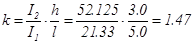
From table 2 beff=1.0 m, hf/h=0.17/0.50=0.34, bw/beff=0.30 μ=0.0417   I=0.0417×1.0×0.503=52.125×10⁻⁴ m4

The loads on the crossbar of each frame are:

Self-weight:  go=0.30m×(0.50-0.17)m×25.00kN/m3         = 2.50 kN/m

Dead loads on slab:                 gs=2.00m×5.25kN/m2  =10.50 kN/m

Additional dead loads:              gw                                      =20.00 kN/m

Total dead loads:                     g                                        =33.00 kN/m

Live load on slab:                    q=2.00m×5.00kN/m2     =10.00 kN/m

Τhe self-weight of each column is 0.40×0.40×3.00×25.00=12.00 kN. Τhe 1/3 of this load (4.00 kN) is applied on the column head and the rest 2/3 of the load (8.00 kN), are applied on the column base.

The dynamic mass of each crossbar in all seismic combinations corresponds to design load:

Pd=(g+ψ2×q)×l+2columns×4.00kN=(33.00+0.30×10.00)×5.00+8.00=188.00 kN

while the seismic force applied on each crossbar is W= (ax /g)×Pd=0.65×188.00=122.00 kN.

In the following analyses implemented manually, the function of rigid bodies will not be considered. In each frame three analyses are performed, one for dead loads G, one for live loads Q and one for seismic loads in +X direction.

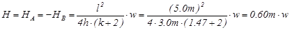
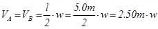
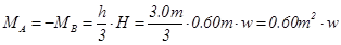
The general analysis of the frame subjected to vertical uniform load w, from table 1 is:

,


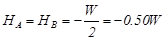
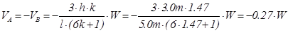
The general analysis of the frame subjected to horizontal load W, from table 39 is:


For load g=33.0 kN/m:

MA,g=-MB,g =0.60m2×33.0kN/m=19.8 kNm

MCA,g =MCD,g =MDC,g =-MDB,g =-1.20m2×33.0kN/m =-39.6 kNm,

HA,g =-HB,g =0.60m×33.0kN/m=19.8 kN, VA,g =VB,g =2.50m×33.0kN/m=82.5 kN

For load q=10.0 kN/m:

MA,q=-MB,q =0.60m2×10.0kN/m=6.0 kNm, MCA,q =MCD,q =MDC,q =-MDB,q =-1.20m2×10.0kN/m=-12.0 kNm,

HA,q =-HB,q =0.60m×10.0kN/m=6.0 kN, VA,q =VB,q =2.50m×10.0kN/m=25.0 kN

For load W=122.0 kN:

MA,W=MB,W =-0.826m×122.0kN=-100.8 kNm, MCA,W =MCD,W =-MDC,W =MDB,W =0.674×122.0=82.2 kNm,

HA,W =HB,W =-0.50×122.0kN=-61.0 kN, VA,W =-VB,W =-0.27×122.0kN=-32.9 kN


1st combination

2nd combination

3rd combination

Combinations and Envelopes of stress resultants

Calculations performed by using the related software

Project <B_331>. The model of the structure, created by the software, consists of slabs, nodes, members, rigid bodies and diaphragms

The moments and shears of the slab are displayed by pressing the corresponding buttons on the left of the screen. The results are the same with the theoretical results of the analysis of the previous paragraph.

The model of the structure, created by the software, comprises members, located on the centroidal axes of the columns and on the central axes at the top faces of the beams. The column-beam connections are modelled by rigid bodies, placed along the direction of beams.

The diaphragm of the slab connects the two frames.
br/> The Interface allows the user to see the numbering of master and slave nodes. Moreover the user can select a node or a member and retrieve their geometrical and loading data. Most of their properties can be modified by selecting ‘Properties’ from the menu.

Τhe software displays the effective area of the slab on each frame, the total dead linear load g=34.5 kN/m and the total live linear load q=10.8 kN/m. The slightly augmented values of g and q used by the software are due to corrections made for taking into account the slab loads that extend beyond both frame ends.

Τhe results of the three combinations from the software are given in the following diagrams of bending moments and shear forces (the elastic line is also shown).

The small discrepancies between practical and automatic (via the software) calculations are due to the fact that the software uses rigid bodies and takes into account work done by shears and axial forces.

Combinations and Envelopes of Bending Moments performed by using the related software


Envelope of bending moments.
The values given per 0.20 m are needed for the reinforcement design and the reinforcement detailing