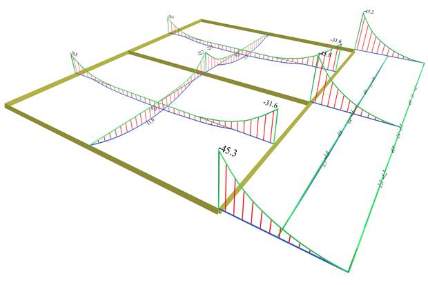
The most unfavourable bending moments are equal to:
Two-way in x: Μx=11.9 (8.0), Mx,erm=-22.8 (-19.9) [kNm]
Cantilever in x: small moments
Two-way in y: Μy=6.0 (4.9), My,erm,1=-20.5 (-17.4) and My,erm,2=-31.6 (-30.6) [kNm]
Cantilever in y: extended My,erm =-31.6 (-30.6), peak -45.8 (-41.3) [kNm]
The differences between the unfavourable bending moments and the bending moments due to global loading, range from 15 to 50%
.