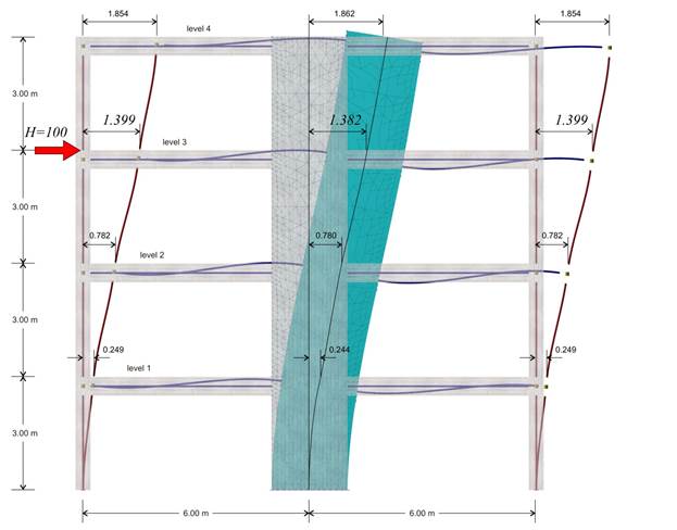
The deformation of the structure
Second analysis results: The displacement of the crossbar at the 3rd level, due to horizontal force H=100.0 kN, is δ3,2=1.399 mm, therefore its stiffness yields K3,1=H/δ3,1=100.0·103N/(1.399·10-3m)=71.5·106 N/m.
The following elastic displacements δi,1 and stiffnesses Ki,1 are obtained from similar analyses applying force H=100 kN separately on each floor i.
4th level: H=100 kN, δ4,2=2.783 mm, K4,2=35.9·106 N/m
3rd level: H=100 kN, δ3,2=1.399 mm, K3,2=71.5·106 N/m
2nd level: H=100 kN δ2,2=0.543 mm, K2,2=184.0·106 N/m
1st level: H=100 kN, δ1,2=0.117 mm, K1,2=855.0·106 N/m
In the example considered, at the 3rd level, the stiffness obtained using finite element modelling is (71.5-64.4)/64.4=11% higher, while at the 4th, 2nd and 1st level 9%, 16% and 25% higher, respectively.
Conclusion: The frame stiffness slightly differs when walls are modelled with two-dimensional finite elements.