en-USes-ES
Menu

One-storey plane frames


Materials
To be continued >
Introduction

Bending and shearing effect on deformations and stresses
Fixed-ended column

Fixed-ended column:

Frames are composed of connected columns and beams behaving as one uniform structure i.e. plane frames comprise many columns connected through beams or slabs. Engineers or engineering students are more familiar with the effects of gravity loads due to their daily exposure to gravity, in contrast to the effects of horizontal seismic forces that are not a daily phenomenon


The degree of fixity effect of columns
One-end-fixed column


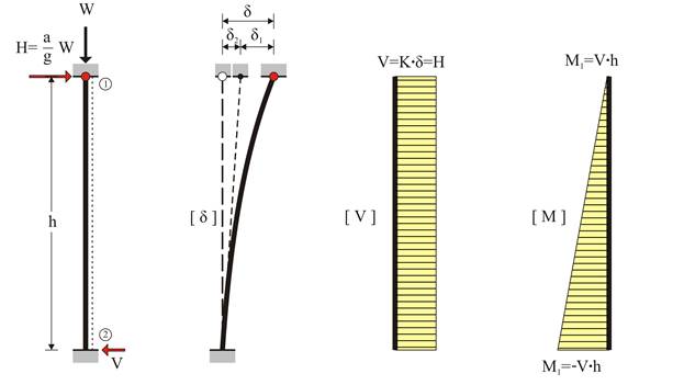
One-end-fixed column:

The fixity degree of a column end, in a specific direction, depends on the relative stiffness between the column and its framing beams.

The fixity degree varies from fixed to pinned. When a weak column (e.g. cross-section 300/300) is connected to strong beams (e.g. concrete beams with height 800mm) the connection could be considered as fixed. On the contrary, when the column top is connected to a plain slab and the column base is connected to weak footing in soft soil without foundation beams, the connections could be idealised as pinned.


The degree of fixity effect of columns
Pin-ended column

In the case of a column pinned at both ends, the equivalent member is not subjected to bending thus carrying neither bending moments nor shear forces. Indicatively, the case of a pin-ended column could be met at a storey without beams, at the roof and at the floor.

Coupled columns (Frames)
(The crossbars are considered having infinite moment of inertia)


80% of the seismic force is carried by the fixed-ended column

In case of seismic action, each column top would be forced to develop identical displacement δ regardless of its stiffness.

The effect of columns moment of inertia
(The crossbar is considered having infinite moment of inertia)

89% and 11% of the seismic action are carried by the strong column (800/400) and the weak column (400/400) respectively

In the one-bay frame of the figure, the second column is considered having eight times higher moment of inertia than the first one.

Example (project <B_513>)

The structural frame model without rigid bodies but fully stiffened

Modelling of the example with elastic degree of fixity on columns

Elastic line, δmax=1.366 mm

Modelling of the example with elastic degree of fixity on columns

Shear force diagrams

Modelling of the example with elastic degree of fixity on columns

Bending moment diagrams

Modelling of the example with elastic degree of fixity on columns

Axial force diagrams

The effect of columns differential height

In the one-bay frame of the following figure, the second column is considered having two times the height of the first one. The crossbar moment of inertia is infinite. Such cases are met in practice e.g. at a store with a mezzanine or in case of a split level foundation.

Shear force diagram

89% of the seismic force is carried by the “short” column.

Bending moment diagram

The bending moment of the “short” column is four times higher than the corresponding moment of the “tall” one.

Frame of common practice (project <B_514>)

In project <B_514> of the related software, the cross-section of the left column C1 and the right column C2 are 400/400 and 800/400 respectively. Their heights are 3.00 m and 6.00 m respectively. The flanged beam cross-section is 250/500/1010/150 and its span is 5.00 m.

Modelling of the example with actual fixity degrees on columns
i.e. those derived from the structural analysis

Elastic line, δmax=6.468 mm

Modelling of the example with actual fixity degrees on columns
i.e. those derived from the structural analysis

Shear force diagrams

Modelling of the example with actual fixity degrees on columns
i.e. those derived from the structural analysis

Bending moment diagrams

Modelling of the example with actual fixity degrees on columns
i.e. those derived from the structural analysis

Axial force diagram