en-USel-GRes-ES
Menu

Lap-splices


Materials
To be continued >
Introduction

Lap-splices of shear wall vertical bars

Generally, the lap length is not extremely large because the vertical rebars’ diameter is usually small. For a typical diameter Ø10/B500c, the required lap length is equal to 540 mm, for concrete grade C30/37. For welded wire meshes the lap length is the 70%, thus 0.70*540=380 mm for the particular example.

Detail of lap-splices of shear wall vertical bars

The lapping of the vertical reinforcement placed to the shear walls’ body: there are no stirrups thus the vertical co-linearity of the rebars is not necessary. In walls’ bodies lapping is being done with the use of a simple contact lap-splice parallel to the longitudinal axis of the element.

(a) Anchorage of rebars in the shear wall body

i) With hooks


ii) With an additional Π rebar


Bars must be anchored at the upper end of shear walls. This anchorage must be done according to the same rules that apply to the anchorage of column rebars. However, as a rule, it is a simpler procedure, due to the smaller diameter of the vertical reinforcement placed inside the wall’s body and also due to the possibility of rebar lapping with a contact lap-splice.

(b) Anchorage of rebars inside an adjacent slab
i) Having a slab on one side only


In case the upper part of the shear wall has only one side connected to a slab, anchoring the outer vertical rebars in the slab’s upper fiber may also contribute in ensuring that the support of the slab is fixed.


An alternative solution is to place a ‘L’ shaped wire mesh.


(b) Anchorage of rebars inside an adjacent slab
ii) Having a slab on both sides

In case the shear wall has slabs on either side, its rebars can be anchored inside the slabs’ mass and at the same time they can be a part of the required slab support reinforcement.

Starter bars in shear wall

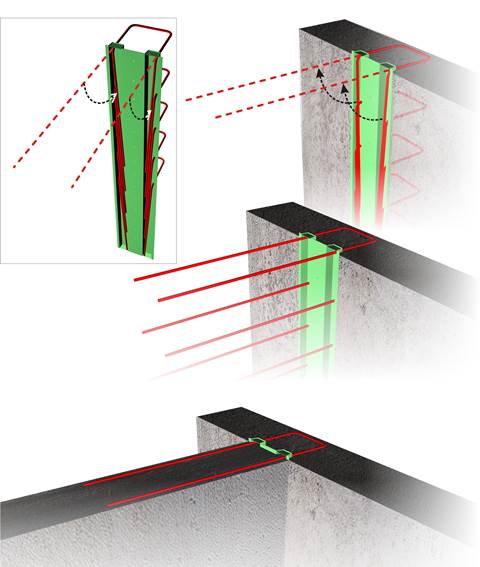
In the cases where the new shear wall will be perpendicular or aligned with the existing one and the starter bars are bound either to cause problems in further excavations or to be damaged by handling machines, the special technique described below is being used:

(a) The starter bars are shaped like a hair pin, their legs are temporarily bent and they are encased in a standardized steel or in an improvised (e.g. made out of polystyrene) thin box,

(b) The thin box is nailed to the formwork. Then follows the positioning of the first shear wall reinforcement and finally comes the concrete casting,

(c) After the formworks removal, the starter bars are once again straightened. If the encasing box had been an improvised construction, it is removed.

(d) The second shear wall is constructed.