en-USel-GRes-ES
Menu

The effect of tortional stiffness (es-ES)

The structural frame
The construction (es-ES)
The reinforcement I (es-ES)
The reinforcement II (es-ES)
Quantity/Cost estimation (es-ES)
Detailing drawings (es-ES)
Tomo A´ - Introducción

Materials (es-ES)
To be continued > (es-ES)
Tomo C´ - Introducción

The effect of torsional stiffness on indirect beam-beam supports

Frame beam supported on bearing beam of another frame

In project <b_334-1> of HoloBIM, the supporting beam b1 has cross-section 300/500 and span l1=4.0 m, whereas the supported beam b2 on b1 has identical cross-section 300/500 and span l2=5.0 m.

Effective torsional stiffness 100% of full torsional elastic stiffness

Bending moment diagrams of the structure

If the effective torsional stiffness of the supporting beam is taken equal to 100% of its corresponding full torsional elastic stiffness, then the bending moment of the left (indirect) support of the supported beam b2 is equal to M=-40.4 kNm.

Torsional moment diagrams of the supporting beam
(Effective torsional stiffness taken equal to the 100% of the full elastic stiffness)

At the left (indirect) support of the supported beam b2 the reinforcing bars, designed for bending moment M=-40.4 kNm should be placed at the top fibers and anchored inside the supported beam b1. In the span, the reinforcing bars, designed for bending moment M=87.9 kNm should be placed at the bottom fibers. The bending moment of the supported beam b2 transfers a torsional moment MT=M/2=40.4/2=20.2 kNm onto the supporting beam b1, as shown on the corresponding diagram of torsional moments. In conclusion, the supporting beam b1 should be designed for torsion.

Torsional deformation of the supporting beam b1

Provided that the structure is suitably reinforced and the formwork remains in place after concreting until the application of all design loads, when the formwork is dismantled, the structural system will behave according to the assumptions made during the calculations, i.e. elastically. Afterwards, beam b1 will start to behave plastically due to creep. The lack of negative reinforcement or its inappropriate anchorage contributes positively to the plasticity of beams.

Detail of torsional deformation in the middle of the supporting beam b1

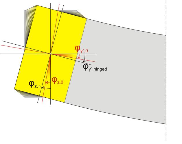
φz,0: the elastic angular deformation at time t=0
φz,∞.: the elastic angular deformation at time t=∞

  The rotation angle of the supporting beam b1 in coordinate system xyz     (φz,0) will be equal to the rotation angle of the supported beam b2 in coordinate system x’y’z’ (φ y’,0), i.e. φz,0= φy’,0 .

The rotation angle φz,t of the supporting beam b1 will be increasing over time t, due to creep. As φy’,t=φz,t, the equivalent angle φy’,t of the supported beam b2 will also be increasing. Consequently, the bending moment M and the equivalent torsional moment MT will be increasing, since MT=M. At a time t=, the system will balance at an angle φy’, =φz, , which cannot exceed the angle φy’,pinnd. The φy’,pinned corresponds to the tangent of the elastic line at the left end of the supported beam b2 when the support there becomes pinned (MT=M=0).

This is why the European Standards [EC2, §5.3.2.2(2)] allow us to consider pinned supports for both beams and slabs. Otherwise, either the creep should be taken into account or the effective stiffness should be limited to a small percentage (e.g. 10%) of the full elastic stiffness.

The assumption of zero torsional stiffness provides a solution in the case of a simply supported beam. However, in the case of a cantilever beam, this turns out to be invalid, because the isostatic structure becomes a mechanism by diminishing its rotational restraint and thus transforming the support from fixed to pinned.

The assumption of effective torsional stiffness limited to 1% of the elastic stiffness gives the correct results for both frames and thus for all types of frames.


Effective torsional stiffness 100% of full torsional elastic stiffness

Bending moment diagrams of the structure

In the case of the simply supported beam b2, with an effective torsional stiffness 1% of the respective full elastic one, the indirect support of b2 on b1 practically behaves as pinned without transferring any torsional moment to the supported beam b1. The beam b2 should be designed only for bending moment M=110.9 kNm along its span, which is significantly greater than the moment 87.9 kNm of the previous case with an effective torsional stiffness equal to the full elastic one.

Cantilever beam supported on bearing beam of the frame

Effective torsional stiffness equal to 1% of the elastic stiffness, project  bending moment, (2) torsional moment <b_334-2>

The support of the cantilever beam, on the bearing beam of the frame, behaves as fully restrained and transfers the moment of the support (-64.1 kNm) as a torsional moment to the bearing beam.In an isostatic structure with respect to torsion, such as structure II, no matter how small the torsional stiffness of the bearing beam is, the torsional moments remain intact.

Notes
  • In general, the torsional stiffness of beams should be considered insignificant at least on site-casting.
  • Similar functionality is also provided for the slab-beam support as shown in the next paragraph.