en-USel-GRes-ES
Menu

Structural model (es-ES)

The structural frame
The construction (es-ES)
The reinforcement I (es-ES)
The reinforcement II (es-ES)
Quantity/Cost estimation (es-ES)
Detailing drawings (es-ES)
Tomo A´ - Introducción

Materials (es-ES)
To be continued > (es-ES)
Tomo C´ - Introducción

Effective span of beams and slabs [EC2 §5.3.2.2]

leff=lnleftright  where α=min(t/2,h/2)


·         At the end support of the first slab, the width is considered to be a=t1/2=125 mm which is acceptable as in favor of the safety.

·         The width of beam-column supports, is taken into account more efficiently, when the analysis uses rigid bodies (see next paragraph).


Effective flange width of continuous beam [EC2 §5.3.2.1]

Continuous beam: lo distance between consecutive points of zero moments 


Effective flange width of continuous frame beam

Continuous frame beam: lo distance between consecutive points of zero moments

Earthquake resistant structures require strong columns and fixed column-beam connections. This requirement demands the creation of a frame set of beams, forming a continuous structure with respect to geometry, but autonomous with respect to the adjacent beams. This fact leads to the conclusion that, in general, the supports of a beam are rarely pinned. Therefore, lo=0.70×l can be chosen for all the earthquake resistant beams.

Effective flange width parameters

beff=bw+beff,1+beff,2≤blim where beff,1=0.20×b1+0.10×lo≤0.20×lo and beff,2=0.20×b2+0.10×lo≤0.20×lo.


·         Τhe effective widths at supports have practical meaning mainly for the dimensioning of  inverted concrete beams under bending.

·         When an adjacent slab is cantilever, of a span ln, the corresponding b1 or b2 is equal to ln.

Rigid bodies

The actual structure and the space model (screen shot captured by HoloBIM)

The space frame model comprises nodes (e.g. node 1, 5, 9 etc.) and members (e.g. member 1, 2, 5 etc.). Nodes are symbolic geometric points where members end. 

In general, each node has 6 displacements (6 degrees of freedom), three translations δx, δy, δz and three rotations φx, φy, φz. The objective of the analysis is the calculation of the 6 displacements for all nodes.

Detail of rigid body


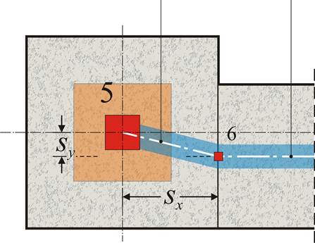
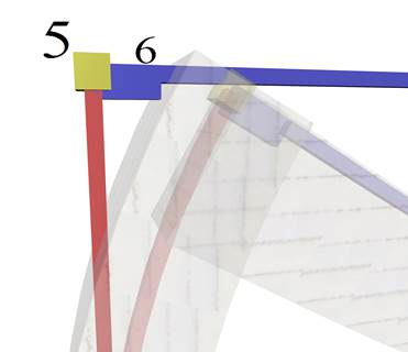
Plan and 3D of column-beam nodes: Master node (5) and slave node (6)


Provided the 6 displacements of the master node are δxδyδzφxφyφz, the corresponding δx,sδy,sδz,sφx,sφy,sφz,s of the slave node are:


φ x,s = φ x , φ y,s = φ y , φ z,s = φ z , δ x,s = δ x -sy × φ (given sz=0), δ y,s = δ y +sx × φ (given sz=0),

δ z,s = δ z -sx × φ y +sy × φ x

Diaphragmatic behaviour

Diaphragmatic behaviour of floor and the displacements of a random point i of the diaphragm due to φz

The 3 displacements δzφxφy of each node belonging to the diaphragm are independent of each other, while the rest δxδyφz are depended on the 3 displacements of point CT called Center of Elastic Torsion of the diaphragm. Displacements δxiδyiφzi at the point i of the horizontal diaphragm are expressed as:

φzi=φz, δxi=δxCT-yi×φz, δyi=δyCT+xi×φz