en-USel-GRes-ES
Menu

Continuous beam (es-ES)

The structural frame
The construction (es-ES)
The reinforcement I (es-ES)
The reinforcement II (es-ES)
Quantity/Cost estimation (es-ES)
Detailing drawings (es-ES)
Tomo A´ - Introducción

Materials (es-ES)
To be continued > (es-ES)
Tomo C´ - Introducción

Continuous frame of 250 x 500 mm section beams

< project: beams20>


Rebar detailing drawings of the two continuous frame beams

As far as the reinforcement is concerned, the construction of a continuous beam with no seismic behaviour requirements is much simpler compared to the earthquake resistant beams.


Placing rebars along the length of the beams

In two successive beams that have the same section, the longitudinal rebar pairs placed both inside the upper and lower stirrup corners are aligned and therefore it is necessary for the one to be slightly bent so as to bypass the other. This bending must be vertically done in order to allow adequate space for the proper concreting.

Placing rebars in a beam cross section : case (1)

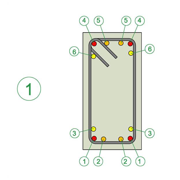
Case (1) shows, in priority order, the possible rebar positions in a rectangular 250/500 beam (with no slab on top).
At the lower part of the beam, the first rebars to place are the corner bars 1, then the internal bars 2 followed by one bar 3 or if it is necessary by a second bar 3.
At the upper part of the beam the same logic apply as well.

Placing rebars in a beam cross section : case (2)

Case (2) shows a “L” section beam where, at the upper part, the priority 6 is given to the rebar placed outside the perimeter of the stirrup. The bar 6 must be positioned at a distance around 20 mm away from the stirrup so as to avoid damage during additional operations by plumbers, electricians etc. This bar should be fitted upon the slab rebar chairs or upon the upper leg of the stirrup, which may close outside the beam’s body.

Placing rebars in a beam cross section : case (3)

Case (3) shows a “T” section beam, where at the upper part the priority 6 is given to the rebars outside the perimeter of the stirrup.

Placing rebars in a beam cross section : case (4)

The case (4) shows in priority order, the possible rebar positions in a rectangular 350/500 beam with a four legged stirrup. It is mandatory to place firstly the corner bars 1, then one rebar 2 and the second rebar 2 followed by the rebars 3. If the reinforcement requirements are so large that cannot be met by an increase in the rebar diameter, bars 4 and 5 of the second layer are subsequently placed one by one.