en-USel-GRes-ES
Menu

Reinforcement quantity take-off (es-ES)

The structural frame
The construction (es-ES)
The reinforcement I (es-ES)
The reinforcement II (es-ES)
Quantity/Cost estimation (es-ES)
Detailing drawings (es-ES)
Tomo A´ - Introducción

Materials (es-ES)
To be continued > (es-ES)
Tomo C´ - Introducción

Ground floor - Slabs

Elem.

Description

Sketch

L
(m)

Quant.
(n)

Length
(L*n)

D.
Ø

S1

upper x

4.42

24

105.98

10


lower
x


4.33

25

108.25

10


lower
y


4.93

16

78.88

8


addi-tional

0.81

15

12.14

8


additional

0.81

15

12.14

8

REBARS QUANTITY TAKE-OF


Diam.
Ø

Mass/m
(Kg)

Quantity
n

Total length
L*n (m)

Additional Mass
b (Kg)

Total Mass
L*n*sw + b (Kg)

8

0.395

46

103.16

0.0

40.7

10

0.617

49

214.23

0.0

132.1

Sum

-

95

-

0.0

172.8


Ground floor - Beams

Element

Description

Sketch

L
(m)

Quant.
(n)

Length
(L*n)

Diam. Ø

0b1

lower


4.28

1

4.28

14


lower


5.33

3

16.00

14


upper


5.37

2

10.75

14


additional
upper


1.75

1

1.75

14


additional

upper


1.75

1

1.75

14


stirrups


1.61

31

49.85

8

0b2

Same as 0b1

REBARS QUANTITY TAKE-OFF

Διαμ.
Ø

Diam.
Ø

Mass/m
(
Kg)

Quantity
n

Total length
L*n (m)

Additional mass
b(Kg)

Total mass
L*n*sw + b (Kg)

4

14

1.210

16

69.07

0.0

83.6

Συνολικά

Sum

-

16

-

0.0

83.6


STIRRUPS QUANTITY TAKE-OFF

Diam.
Ø

Mass/m
(
Kg)

Quantity
n

Total length
L*n (m)

Additional mass
b (Kg)

Total mass
L*n*sw + b (Kg)

8

0.395

62

99.70

0.0

39.3

Sum

-

62

-

0.0

39.3

Ground floor - Columns

Element

Description

Sketch

L
(m)

Quantity
(ν)

Length
(L*v)

Diam.
Ø

0C1

Cor-ner

3.15

4

12.62

16


Top

3.13

4

12.53

16


Stirrups


1.24

30

37.06

8


Stir-rups


1.61

30

48.24

8

0C2 , 0C3, 0C4 : The same as 0C1

REBARS QUANTITY TAKE-OFF

Diam.
Ø

Mass/m
(
Kg)

Quantity
n

Total length
L*n (m)

Additional mass
b (Kg)

Total mass
L*n*sw + b (Kg)

16

1.580

32

100.60

0.0

159.0

Sum

-

32

-

0.0

159.0

STIRRUPS QUANTITY TAKE-OFF

Diam.
Ø

Mass/m
(
Kg)

Quantity
n

Total length
L*n (m)

Additional mass
b (Kg)

Total mass
L*n*sw + b (Kg)

8

0.395

240

341.21

0.0

134.6

Sum

-

240

-

0.0

134.6

ESTIMATE OF CONCRETE (m³)

Level

Superstructure

Foundation

Sum (m3)


Slabs - Beams

Columns

Foundation


Ground floor

4.97

1.60


6.6

Basement

5.41

3.85

5.51

14.8

TOTAL (m3)

10.38

5.45

5.51

21.3

ESTIMATE OF FORMWORK (m²)

Level

Superstructure

Foundation

Sum (m2)


Slabs - Beams

Columns

Foundation


Ground floor

31.78

16.00


47.8

Basement

35.24

32.75

21.72

89.8

TOTAL (m2)

67.02

48.75

21.72

137.6

REINFORCEMENT ESTIMATE (m)(kgr)


Superstructure

Foundation

Sum

Rebars

Slabs

Beams

Columns

Slabs

Footings

Beams

(m)

(Kgr)


Ø8

129.98

-

-

-

-

-

329.42

129.98


Ø10

132.08

-

187.11

-

-

-

517.72

319.19


Ø12

-

-

-

-

76.17

61.14

154.65

137.30


Ø14

-

192.65

-

-

-

-

159.22

192.65


Ø16

-

-

395.05

-

-

197.17

374.83

592.23

Total rebars qties

262.07

192.65

582.16

-

76.17

258.31

1535.83

1371.36

Stirrups

Slabs

Beams

Columns

Slabs

Footings

Beams

(m)

(Kgr)


Ø8

-

92.89

309.72

-

-

-

1020.34

402.61


Ø10

-

-

-

-

-

86.32

140.00

86.32

Total stirrups qties

-

92.89

309.72

-

-

86.32

1160.34

488.92

TOTAL

262.07

285.54

891.88

-

76.17

344.63

2696.17

1860.28

1st example (one-way slab)

<project: slabs10 >

In the example of the one-way slab in §3.5.1 the total slab length was 4.40 m and the length of the lower rebars was 4.33 m.
In both ends of the slab, the side formwork might slip to the left or to the right around 20 mm therefore, in the two worst cases, the slab’s span length may take a value between 4.40-0.02-0.02=4.36 m and 4.40+0.02+0.02=4.44 m. Rebars are critically affected when the slipping of the slab’s ends happens towards the inside. In order to avoid such a case and have the proper cover depth, the lower rebars must be formed with a length equal to 4.33-0.02-0.02=4.29 m.
The standardized cut length is 4.25 m or 4.50 m. In this case, it is not possible to cut the rebar to a length either shorter (than 4.25 m) or longer (than 4.50 m) and therefore the optimization regards only the constructional deviation. Consequently, the rebars (2) must be cut to a length of l2=4.29 m instead of 4.33 m. The same logic applies to rebars (5) as well, which will be cut to a length equal to l5=4.29 m rather than 4.33 m.

2nd example (continuous slabs)

<project: slabs30>


The effect of ‘constructional deviation’ upon the optimization:


The constructional deviation of the two slabs does not affect the majority of the rebars’ lengths because it is possible for the latter to move to the adjacent slabs. Rebars (3) are the only ones that have limitation and since they do not have a margin either to the left or to the right, they must be formed with a length equal of 5.54 m instead of 5.58 m. For the same reason the vertical bars (4) and (7) must be formed with a length equal to 4.89 m rather than 4.93 m.

 The effect of ‘standardized cut’ upon the optimization:

The rebars (1) must have a length of 5.50 m instead of 5.52 m due to a minor difference (where the left upper horizontal part of the bent-up rebar becomes 0.72 m instead of 0.73 m and the right upper horizontal part becomes 0.181 m instead of 0.182 m).

The rebars (2) will be formed with a length equal to 4.50 rather than 4.33.

The rebars (5) will be 3.00 m long instead of 2.78 (where the last length will become 2.65 instead of 2.43)

The rest of the rebars have a limitation and cannot be standardized therefore, the bars (4) and (7) will be formed with a length equal to 4.89 rather than 4.93.


3rd example (simply supported beam)

<project: beams10>

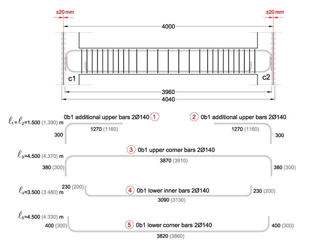
In the example of the simply supported beam in § 3.4.1 the beam is 4.00 m long and therefore, the total length may vary between 3.96 m and 4.04 m. The constructional deviation does not affect the support rebars (1) and (2), which will be formed with a total length equal to 1.50 m instead of 1.39 (where the last length will become 1.27 rather than 1.16).

The lower and upper rebars of the beam are affected by the constructional deviation. This is the reason why the bars length must be shortened by 40 mm, however, the hooks may become larger so as to achieve the required final length (hooks must not extend outside the concrete’s mass and must abide by the necessary beam’s cover thickness).

The rebars (3) will have a total length of 4.50 m instead of 4.37, with a span length equal to 3.87 rather than 3.91 and their hooks will be 0.38 long instead of 0.30.

Consequently the reinforcement bars (4) will have a total length equal to 3.50 m rather than 3.48, with span length 3.09 instead of 3.13 and their hooks will be 0.23 long rather than 0.20.

The rebars (5) will have a total length of 4.50 m instead of 4.33, with span length equal to 3.82 rather than 3.86 and their hooks will be 0.40 long instead of 0.30.

 For further details into the quantity take-off matter but also for all the various matters discussed, it is advisable to study the corresponding printed book.