en-USel-GRes-ES
Menu

Strip foundation (es-ES)

The structural frame
The construction (es-ES)
The reinforcement I (es-ES)
The reinforcement II (es-ES)
Quantity/Cost estimation (es-ES)
Detailing drawings (es-ES)
Tomo A´ - Introducción

Materials (es-ES)
To be continued > (es-ES)
Tomo C´ - Introducción

One-bay frame with strip foundation that extends (beyond the columns) on both sides

<project:foundation140>

The strip foundation is the foundation element that behaves, simultaneously, like a spread footing and a beam.
The strip foundation (inverted T-beam) behaves in a way similar to that of spread footings tied together by a connecting beam. However, due to the fact that the footing and the inverted T-beam’s web form a unified body along the entire length of the structure, the system’s inertia is larger therefore, its behaviour is more satisfactory

Behaviour of one-bay frame with strip foundation (no seismic loads applied)

When no earthquake loads are applied, the soil stresses are symmetrically distributed in the entire length of the strip foundation. The soil stresses are higher in the area of columns.

Behaviour of one-bay frame with strip foundation (under seismic loads)

During an earthquake, loading on one edge is higher thus creating higher soil stresses while at the same time the other edge is relieved. When the seismic forces shift direction the footings’ loading switches symmetrically. The deformations and stresses applied to the strip foundation are high and continuously alternating.
The footing behaves like a bilateral cantilever (fixed upon the strip foundation’s web). Its behaviour is similar to the behaviour of the spread footings therefore it requires reinforcement at its lower fiber, as shown at the figure below.

Footing slab behaviour

The soil’s reaction, loads the footing slab (the inverted T-beam’s flange) in an upward direction. This causes deformations at the lower surface of the footing which are carried by the reinforcement.

Strip foundation behaviour under seismic loads

< project:foundation145>

Strip foundations behave extremely well during an earthquake. Depending upon the seismic forces’ direction one edge is heavily loaded. In large parts of the strip foundation, the deformation continuously reverses and therefore, it requires strong reinforcement both at the upper and lower fibre, especially at the first and last opening of a continuous strip foundation. In order to have a more efficient behaviour of the strip foundation’s edge areas, it is useful to extend the strip foundation beyond the edge columns to an adequate length.

3-D view of the strip foundation reinforcement

<project: foundation150>

The behaviour of this element is quite obvious since the footing (i.e. the flange) distributes the applied loads to the soil, it is loaded by the soil’s reaction and behaves like a cantilever slab while the foundation web behaves in a way similar to a beam.

Strip foundation reinforcement detailing

The flange’s reinforcement follows the same rules that apply to isolated spread footings taking into account however, that one of its dimensions is very lengthy.
The web’s reinforcement follows the same rules that apply to connecting beams. Its reinforcement details are analogous to the corresponding reinforcement details of the previously mentioned continuous connecting beam.

Reinforcement of orthogonal strip foundation

<project:foundation160>

In a strip foundation having the web and flange of equal depth (i.e.orthogonal section), the footing’s (web’s) total depth is equal to the web’s height. The only difference between the normal strip foundation and the strip foundation with an orthogonal cross section is the fact that the latter requires reinforcement at the “flange’s” upper surface.
In the case of a strip foundation where the flange and the web have the same dimensions a hidden beam is formed.

Reinforcement detailing of strip foundation with unified web-flange

The foundation wall reinforcement details of this specific strip foundation are similar to the reinforcement details of the previously mentioned continuous connecting beam.

Strip foundation in which the web extends beyond the column face

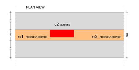
The column with 800/250 section, in the common wall of the building, is partially supported by the strip foundation that has a web of 350/800. In general at joint areas either at the superstructure or the foundation, it is advisable to place stirrups in the columns and the beams. However practically, this is a strenuous procedure and therefore, it is preferred, as a priority, to place stirrups inside the columns.
When the web sides are not flush with the sides of the column (e.g. web wider than the column), additional transverse reinforcement is required. This reinforcement may be provided in the form of the beam’s regular stirrups or additional stirrups in the shape of a hairpin positioned as shown at the following figures.

Wall reinforcement of strip foundation, that extends beyond the column, with additional hairpin bars

After the placement of the stirrup cages inside the inverted T-beam web, the web’s part that extends beyond the column remains un-reinforced along the vertical axis. The hairpin bars (in red colour) that will be placed in that area are shaped and placed in a separate phase.
The transverse reinforcement positioned at the column - beam junction area, consists of hairpin - shaped bars subsequently placed one by one. In that area, the vertical reinforcement at the back side of the strip foundation is provided by the column’s longitudinal reinforcement (i.e. from the column rebars).

Two-sided extension of the foundation beam web

The 800/250 column is sited upon the center of the strip foundation beam that has a section of 500/800.

Transverse reinforcement placed inside the web of strip foundation that extends, beyond the column, on both sides

After the placement of the stirrup cages inside the strip foundations’ walls, the wall parts that extend beyond the column remains un-reinforced along the vertical axis.  The double hairpin - shaped rebars (in red colour) that will be placed in that area are shaped and positioned in a separate phase.

The transverse

reinforcement

positioned

at

the

column - beam junction

area

,

consists of

bilateral

hairpin

- shaped

bars

subsequently

placed

one

by

one on both sides of the beam

.