en-USel-GRes-ES
Menu

Beams and columns (es-ES)

The structural frame
The construction (es-ES)
The reinforcement I (es-ES)
The reinforcement II (es-ES)
Quantity/Cost estimation (es-ES)
Detailing drawings (es-ES)
Tomo A´ - Introducción

Materials (es-ES)
To be continued > (es-ES)
Tomo C´ - Introducción

Non-earthquake resistant structural frame

The frame of the figure comprises two columns and one beam and it bears only gravity loads i.e. no seismic loading is applied

Deformations of a non-earthquake resistant structural frame

The figure shows the concrete deformations and cracks. They are presented in a very large scale to provide a thorough understanding of the way the members behave. In reality they are so small that they are not visible to the human eye.
The tensile stresses generated in some areas of concrete cause the formation of cracks; therefore in those areas the necessary reinforcement is placed. When the cracks are perpendicular to the axis of the member, longitudinal reinforcement is placed i.e. rebars that prevent the expansion of the hairline cracking.
When the cracks are diagonal, transverse reinforcement i.e. stirrups is placed to control them.

One-bay earthquake resistant structural frame

<project: frame1>

An earthquake ground motion causes horizontal displacements that in their turn cause horizontal inertia forces, forces created by the sudden change in the kinetic state of the body.
During the seismic action the applied horizontal forces constantly shift direction. This fact results in a continuous change in the frame’s behavior and consequently the tensile stresses and thus the diagonal cracks appear in different positions and directions. This position- direction alteration is the reason why earthquake design and reinforcement detailing are so critical in areas with high seismic activity.

Behaviour of a one-bay frame during an earthquake

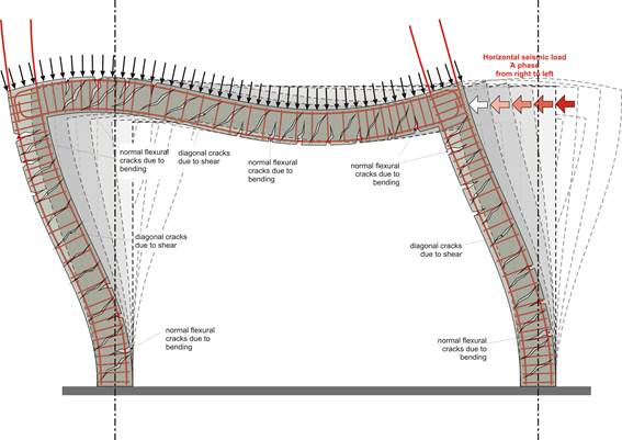
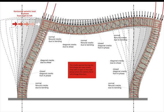
No matter how well designed a structure is, one or possibly more structural members will exceed their design strength, either because seismic forces might exceed the design assumptions or because of local conditions during the construction.

1st Defense mechanism: In case of an earthquake greater than the design earthquake we don’t want failure (fracture) of any member even if it remains permanently deformed, this means that we need ductile structural members.
2nd Defense mechanism: in the case of an extremely intense earthquake, where failure of some members is unavoidable, the elements that must not fail are the columns; this means that the columns must have sufficient capacity-overstrength.
In the second defense mechanism all failures must be flexural because of their ductile nature as opposed to shear failures that have a brittle behavior (i.e. sudden fracture


Structural frame ductility

This figure illustrates a column with cross-section 500x500 and three stirrups on every layer, required by the Seismic Code to ensure ductility

Ductility is the ability of a reinforced concrete member to sustain deformation after the loss of its strength, without fracture.
Ductility i.e. the element’s deformation capability beyond its yielding point concerns flexure and presumes adequate shear strength. For this reason shear design is based on the elements capacity-overstrength so as to avoid potential shear failure.

Beam with ductility requirements

Basic rules for beam reinforcement:
(a) Rebars placed in the beams lower part must be equally well anchored as those placed in the upper part since tension and therefore the resulting transverse cracking, continuously change place during a seismic action and as a consequence in critical earthquakes, tensile stresses appear at the lower fibers of the supports.
(b) There must be plenty of strong transverse reinforcement consisting of dense and well-anchored stirrups because the high intensity of the diagonal stresses and thus the large inclined diagonal cracking, shift direction during an earthquake.
Columns and beams usually fail in the joint area i.e. the area where the beam intersects with the column. Therefore columns and beams must be ductile in the joint area.

Beam with high ductility requirements

If all members of the structure system have enough ductility the structure’s strength capacity will depend upon the strength capacity of all the structural members, otherwise it will be depended upon the strength capacity of the most vulnerable structural member.