en-USel-GRes-ES
Menu

Rebar bending (es-ES)

The structural frame
The construction (es-ES)
The reinforcement I (es-ES)
The reinforcement II (es-ES)
Quantity/Cost estimation (es-ES)
Detailing drawings (es-ES)
Tomo A´ - Introducción

Materials (es-ES)
To be continued > (es-ES)
Tomo C´ - Introducción

The bending of reinforcement bars
Minimum bending pin diameter for bars

The minimum bending pin is Øm,min

Øm,min=4Ø for Ø≤16 mm           Øm,min=7Ø for Ø>16 mm

The minimum diameter Øm (mandrel diameter) to which a bar is bent, shall be such to avoid bending cracks to the bar and ensure the integrity of concrete inside the bent of the bar where large forces appear.  The smaller the mandrel diameter is, the larger these forces are and consequently the concrete may fail thus leading to the disintegration of the cross-section.

Minimum bending pin diameter for wired mesh

The minimum bending diameter in welded wired meshes is Øm,min=5Ø

Bar anchorage with simple hook


Beam bar anchorage with simple hooks and transverse bars (metal pins) ≥Ø within the bent section

The term ‘anchorage’ represents the extension of a reinforcement bar inside the concrete, in order to achieve adequate cohesion of the two materials, steel and concrete. With this specific procedure, steel can contribute up to its maximum strength, whenever it is required. The anchorage can be either straight or hooked.

Apart from the satisfaction of the bending standards, the bent section of a bar is accounted in the overall anchorage length lbd (see  next paragraph ) when the three following conditions are met:

(1)  The anchorage of the bar does not require a length larger than  beyond the bending point,

(2)  At least one transverse bar (metal pins) with diameter ≥Ø is fitted within the bent section,

The bending level is not situated too close to the surface of the concrete.

Beam bar anchorage with simple hooks and 2 welded pins


Beam bar anchorage with simple hooks and 2 welded transverse bars (metal pins) could be ≥0.6Ø within the bent section


Drum anchorage


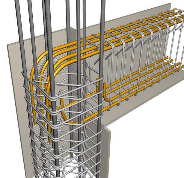
Whenever the above requirements cannot be met, then the anchorage is achieved
with a large diameter drum

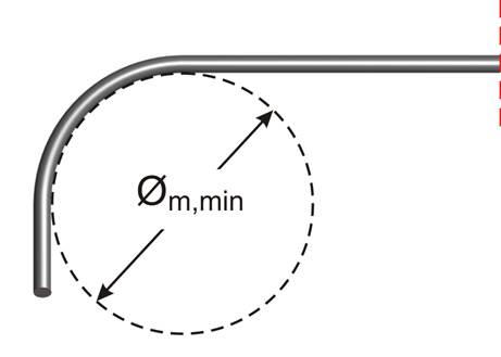
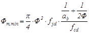
The minimum bend diameter Øm,min depends on the steel strength fyd, the strength of the con-crete fcd, the diameter Ø of the reinforcement bar and the axial distance ab between the adjacent bars according to the following formula:


• For bar or group of bars near the surface of the structural element ab=cover+Ø/2

• Strength fcd always lower than fcd of concrete class C55/67

Column minimum dimension


In case of anchorage of beam reinforcement bars inside a column (which is the most common case), for common concrete, ab=37mm+Φ hence the minimum bend mandrel diameter becomes:

Øm,min=(PI/4)×Ø2×fyd× [1/(37+Ø) + 1/2Ø]/ fcd

For these cases, the minimum dimensions of the column must be:

lmin=cnom+ Østir+ Ø + Øm,min/2+5Ø

Minimum diameters of bend bar anchorage and minimum column dimensions lmin where these bars are anchored

For steel B500c (fyd=434.78MPa) and γc=1.50 and for cnom=35mm, Østir=10mm

Ø (mm)


12

14

16

18

20

22

25

28

32

40

fck(MPa)

mm

mm

mm

mm

mm

mm

mm

mm

mm

mm

mm

12

Øm,min

382

463

548

636

726

820

964

1112

1316

1741

lmin

310

360

410

470

530

590

680

770

900

1160

16

Øm,min

286

347

411

477

545

615

723

834

987

1305

lmin

260

300

350

390

440

480

560

630

730

940

20

Øm,min

229

278

329

381

436

492

578

667

790

1044

lmin

230

270

310

340

380

420

480

550

630

810

25

Øm,min

183

222

263

305

349

393

463

534

632

836

lmin

210

240

270

310

340

370

430

480

550

700

30

Øm,min

153

185

219

254

291

328

386

445

527

696

lmin

190

220

250

280

310

340

390

440

500

630

35

Øm,min

131

159

188

218

249

281

330

381

451

597

lmin

180

210

230

260

290

320

360

400

460

580

40

Øm,min

114

139

164

191

218

246

289

334

395

522

lmin

170

200

220

250

270

300

340

380

430

550

45

Øm,min

102

123

146

169

194

219

257

297

351

464

lmin

170

190

210

240

260

290

320

360

410

520

50

Øm,min

92

111

131

153

174

197

231

267

316

418

lmin

160

180

210

230

250

280

310

350

390

490

55

Øm,min

83

101

119

139

158

179

210

243

287

380

lmin

160

180

200

220

240

270

300

330

380

480

Example: For bar Ø20, in case of C20, lmin=380 mm, in case of C30, lmin=310 mm and in case of C40, lmin=270 mm